Bradipograph: the sloth-writer

Bradipograph is an open-source build-it-yourself robot for drawing on windows and blackboards. Controlled over bluetooth, it can draw svgs and comes with a library of tools for procedurally generating line drawings.
This book contains instructions to build and run your own bradipograph. Assembly requires a 3d printer, a soldering iron, and about $20 worth of parts.
List of materials
3d printed parts
STL files for 3d printing are available here. The required tolerances are not very tight; any reasonable print settings should be fine.
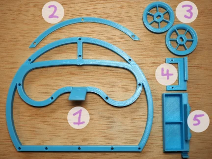
- head
- forehead
- rotors (you'll need two copies)
- servo mount
- battery box
Other parts
Here is a picture of most of the other parts you'll need (I forgot to include the batteries). I've tried to include Amazon and AliExpress purchase links where possible, but they tend to go stale. See the Notes section for more details on the parts, and some advice on substitutions.
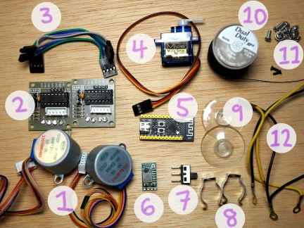
- two stepper motors (28BYJ-48) (amazon, aliexpress)
- two stepper motor drivers (ULN2003); often sold in combination with the motors
- the wires that came with my stepper motors and drivers. You can also just supply your own wires.
- servo motor (sg90) (amazon, aliexpress)
- ESP32-C3FH4 dev board by WeAct Studio (aliexpress)
- DC step down converter, 5v output (amazon, aliexpress)
- Power switch (amazon, aliexpress)
- Terry clips, big enough to firmly hold your markers (amazon, aliexpress)
- Suction cups, (amazon)
- Thread (or fishing line)
- A bunch of M3 screws, and two M2 screws.
- Assorted wires, with "Dupont" style connectors and ring terminals (amazon, amazon, aliexpress, aliexpress)
- Two 9v rechargeable batteries, and two 9v battery connectors (not pictured)
Tools and equipment
- soldering iron
- 3d printer
- screwdriver
- hot glue gun
- tool for cutting and stripping wire
- crimping tool
- USB-C data cable
- computer
Notes
Motors and servos
28BYJ-48 stepper motors are made by many manufacturers, and often packaged with ULN2003 drivers. As of me writing this, a pack of 5 motors and 5 drivers is available for $15 on Amazon or $10 on AliExpress.
The pen is lifted with an SG90 servo, which is also made by many manufacturers. A 5-pack costs about $10 on Amazon, or $5 on AliExpress.
The batteries
I'm using two rechargeable 9v Li-ion batteries. At about $20 for a 4-pack on Amazon, this is definitely the most expensive part. You'll also need two 9v battery connectors with wire leads. A 10-pack is about $5 on Amazon.
Power supply
We'll power the device with 9v batteries, but that 9v needs to be converted down to 5v. Adjustable DC step-down converters are available in packs of 5 for about $10 on Amazon or $5 on AliExpress. Any cheap converter should be fine; we won't draw much current.
The brains
The device is controlled by an ESP32-C3 chip. Development boards with ESP32-C3 chips are available on AliExpress for as little as $2. There doesn't seem to be much difference between the different boards except for the locations of the various pins; probably any of them will work. But if you want to use the exact same board as me, I'm using WeAct Studio's ESP32-C3FH4 Core Board. This seems to be available only on AliExpress.
Pen holder
I'm using two terry clips to hold the marker in place. You can also use a binder clip, a rubber band, or anything else that holds the pen firmly in place.
Wiring
I cut my own wires to approximately the correct length; I connected the wires to the various devices using "Dupont"-style connectors, and I connected the power wires to one another using a screw and ring terminals. You can of course use pre-cut and pre-crimped wires if you prefer.
String
You'll need a few meters of string for hanging the device. Ordinary sewing thread works well (it isn't very heavy), as does fishing line.
Firmware and software installation
Bradipograph needs two pieces of software to run: the firmware that gets flashed onto the bradipograph itself, and the control software that gets run on your computer.
Obtain the feeder
Currently, the control software (the "feeder") is only built and tested on x86_64 linux; a statically-linked executable is available here. After downloading it and marking it executable, you should be able to run it:
./bradipo-feeder --help


Usage: bradipo-feeder [OPTIONS] [COMMAND]

Commands:
  calibrate        Calibrate the bradipograph from scratch
  set-arm-lengths  Re-calibrate just the arm lengths
  set-max-hang     Set the maximum vertical hang
  set-min-angle    Set the minimum hanging angle
  move             Move to a coordinate
  svg              Draw an SVG file
  square           Draw a square showing the drawable region
  query            Query the current bradipograph status
  help             Print this message or the help of the given subcommand(s)

Options:
      --simulate <SIMULATE>  If set, simulates a bradipograph and draws its output to an svg file at the given path
  -h, --help                 Print help
The feeder should also run on Windows and macOS, but you'll need to figure it out yourself; the source code is here.
Flash the firmware
-
Install
espflashby following its installation instructions. -
Download the latest bradipograph firmware and the partition map.
-
Connect your ESP32-C3 (part number 5 in Materials) to your computer with a USB cable. Your device should show up as a serial port; note its name. (On my linux system, it's usually
/dev/ttyACM0.) -
Flash your device:
espflash flash <path/to/bradipograph> -p </path/to/serial> --partition-table <path/to/partition.csv>where you'll replace
<path/to/bradipograph>with the location of the bradipograph firmware you downloaded in step 2,<path/to/partition.csv>with the location of the partition map you downloaded in step 2, and</path/to/serial>with the serial port that appeared in step 3. -
With your ESP32-C3 still plugged in, test it by running the feeder. It should find your bradipograph device and see that it hasn't been calibrated yet:
./bradipo-feeder query
calibration: Uncalibrated
With the firmware set up, you're ready to proceed with assembly.
Assembly instructions
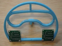
Mount the motor drivers
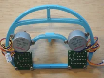
Turn the head face-down, and place a stepper driver face-down in the bottom left-hand corner, with the four LEDs on the driver towards the top of the head. Secure with two M3 screws, then repeat with the other stepper driver in the bottom right-hand corner of the head.
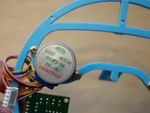
Attach the motors
With the head still face-down, turn one of the stepper motors axle-down and mount it with two M3 screws to the left eye socket. The motor's wires should point towards the bottom of the head, and slightly to the left. Mount the other stepper motor to the right eye socket.
Attach the strings
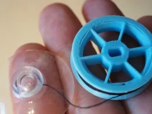
Cut two long pieces of thread. Find the two holes in the rim of one of the rotors. Starting from outside the rotor, insert the end of the thread into one hole, then pass it between the spokes, then bring it back out through the other hole.
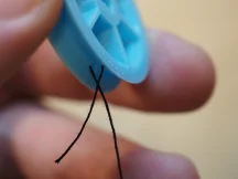
Tie a knot in the thread and cut off the excess.
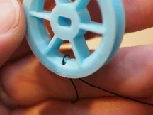
Tie the other end of the thread to one of the suction cups, and wind the thread around the rotor.
Repeat with the other rotor, thread, and suction cup.
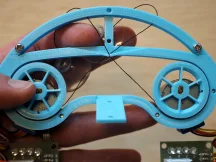
Mount the rotors
Turn the head face-up, and orient one rotor so that the thread winds counter-clockwise around it. Press the rotor onto the axle of the left motor. It should be a snug fit, and may require some force. Pass the thread through the thread guide.
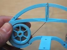
Mount the right rotor, oriented so that its thread winds clockwise. When passing its thread through the thread guide, cross it over the left rotor's thread.
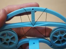
Wind the motor wires around the sides of the head to use up the excess, then plug them into the motor drivers.
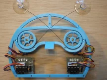
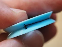
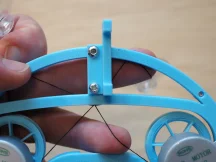
Making sure that the threads are crossed, place the forehead piece over the threads and attach it with two M3 screws. Don't attach the middle screw yet!
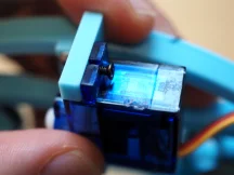
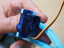
Mount the servo
Turn the head face-down, and mount the servo bracket to the back of the head with two M3 screws. The servo attachment points should be on the right, and extend above the top of the head as shown.
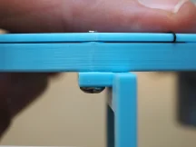
The top screw of the servo mount must be at least 12mm, so it is long enough to extend through the forehead.
Insert the servo into its bracket from the right, with the servo axle towards the bottom of the head. Fasten the servo to its bracket with two M2 screws, passing them through the servo's screw holes first and then into the bracket.
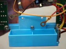
Attach the battery box
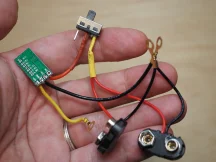
Attach the 9v battery connectors to the voltage converter and the power switch:
- Solder the two positive wires from the battery connectors to center pin of the switch.
- Join the two negative wires from the battery connector, and crimp on a ring terminal.
- Solder a wire from one of the other switch pins to the "IN+" pin of the voltage converter.
- Solder wires to the "GND" and "VO+" pins of the voltage converter, and crimp ring terminals to the other ends.
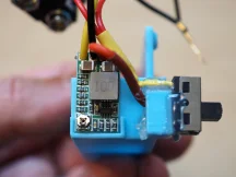
Using a hot glue gun, glue the voltage converter and the power switch to their mounting points at the bottom left of the battery box.
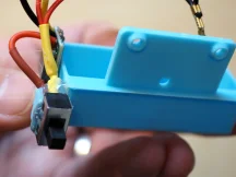
Turn the head face-down, and use an M3 screw to attach the battery box to the bottom part of the head, between the two stepper drivers.
Attach the pen holder
Using M3 screw, attach the two spring clips to the nose.

Wire up the stepper drivers
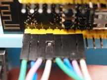
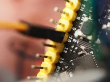
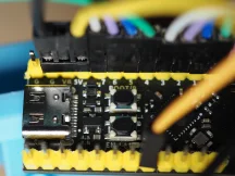
Connect the stepper drivers to the dev board, paying close attention to the orientation. Each stepper driver has four pins in its bottom left-hand corner; pin 1 is on the left and pin 4 is on the right. Connect pins 1, 2, 3, and 4 of the left stepper driver to pins 0, 1, 2, and 3 respectively on the dev board. Connect pins 1, 2, 3, and 4 of the right stepper driver to pins 4, 5, 6, and 7 respectively on the dev board.
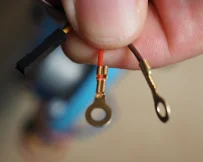
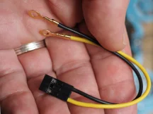
Cut and strip the ends of the servo motor wires. Crimp ring terminals to the ends of the red and brown wires, and crimp a DuPont connector to the end of the yellow wire. Plug the yellow wire into pin 10 of the dev board.
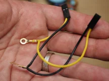
Prepare two 2x1 DuPont connectors for providing power to the stepper drivers: first, crimp a power wire and a ground wire to each connector. Join the two power wires and crimp them to a ring terminal, then join the two ground wires and crimp them to another ring terminal.
Wire up the power
Plug the stepper power connectors into the stepper drivers.
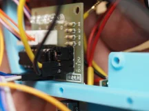
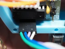
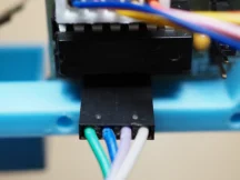
Prepare a 3x1 DuPont connector for providing power to the dev board. Leaving the middle pin empty, crimp a power wire and a ground wire into the two outer pins.
Plug in the dev board power so that the power wire connects to the pin labeled "5V" and the ground wire connects to one of the pins labeled "G".
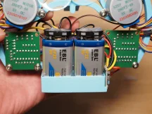
Gather all the 5V power wires (the red wire from the servo, the wire from the "VO+" pin of the voltage converter, the stepper driver power wires, and the dev board power wire). Put an M3 screw through the ring terminals of all these wires and screw it into the left hole on the battery box.
Gather all the ground wires (the brown wire from the servo, the wire from the "GND" pin of the voltage converter, the stepper driver ground wires, the dev board ground wire, and the wire from the negative 9V battery terminal). Put an M3 screw through the ring terminals of all these wires and screw it into the right hole on the battery box.

Plug 9v batteries into the battery connectors, and put them in the battery box.
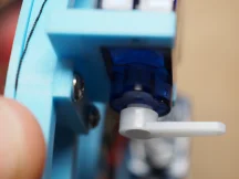
Align the servo motor
Turn on the power switch. The first two leds on each stepper motor should light up, and you should here a sound as the servo moves into position. Turn the power switch off again.
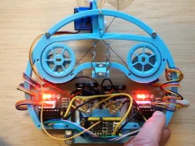
Now that the servo has found its position, attach the little plastic piece to the servo axle so that it points perpendicularly out from the back of the head.
And that's it! Your Bradipograph is assembled and ready to draw.